This is http://icarc.org hosted at n952.ooguy.com
ICARC Fox Hunting
Last updated 15 Jan 2025 by KC0JFQ
Next Fox Hunt
DOA :-( No interest on 09/28 net 04 Oct 2025
CDT
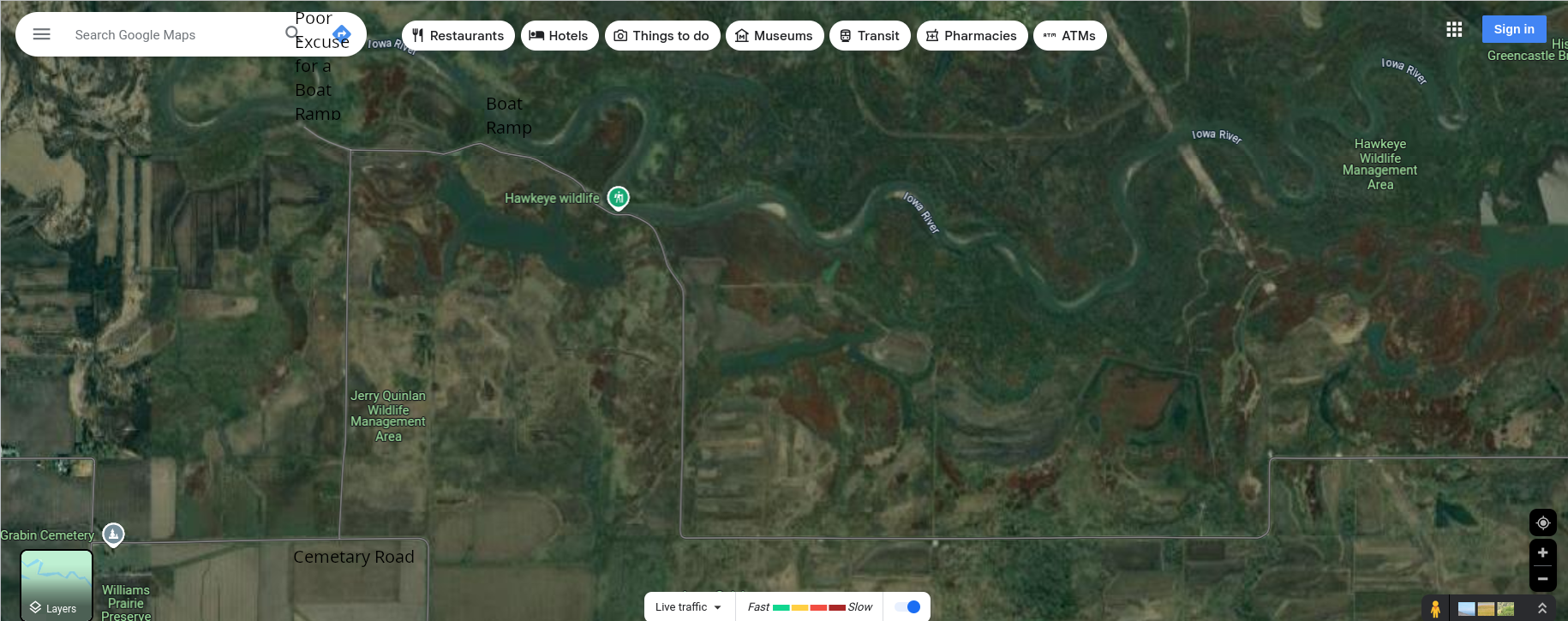
Hickory Hill Park
Conklin Lane
Iowa City, IA
Potential Hunt Venues
Hickory Hill Park
Conklin Lane
Iowa City, IA
approach from North Dodge Street, just east of cemetary
other access points are not vehicle accessible.
F.W. Kent Park
Conservation Education Center.
Parking lot N.E. corner
Terry Trueblood Recreation Are
579 McCollister Blvd
Iowa City, Iowa 52240
Venue for a vehicle-centric hunt along Swan Lake Road
up on the south side of Coralville Reservoir.
You cross under Swan Lake Road when running on I-380,
it is the overpass just north of North Liberty (Exit 4).
The east end of Swan Lake Road is just south of the
Pipeline Depot on Hwy 965.
You can also access it from West Penn Street (250th St NW).
West fronm exit 4 on I-380.
James Ave., Half Moon Ave., Greencastle Ave., and Cemetary Road
all run towards Swan Lake Road.

East Swan Lake Road
The west end of Swan Lake Road runs right along the river
providing a very rustic trip.

West Swan Lake Road
On the equipment front
We have our huge stable of transmitters,
enough to run
THREE hunts concurrently
with 3 extra training transmitters.
The training transmitters are CW only and they
run almost continuously, each on a unique frequency.
There will be THREE hunt groups (three frequencies).
At least 5 transmitters in each group!
This means you will hear near continuous traffic
in each group.
Transmit cycle is 5 or 6 minutes minutes
Each transmitter runs for just less than 1 minute.
As we are operating multiple frequencies,
here is a list:
Operating
Frequency |
Transmitter
in group |
Cycle
Period |
On Time |
Comments |
Transmitter
Hardware
|
|---|
| 144.150 MHz
| All Hunt
Groups
| Startup
Message
| about 15 sec
| Reporting
Frequency
All Groups
| all!
|
| 144.225 MHz |
6 |
6 minutes |
< 55 sec |
Hunt Group 1 |
102-73181-10 |
| 144.325 MHz |
6 |
6 minutes |
< 55 sec |
Hunt Group 2 |
102-73181-10 |
| 144.250 MHz |
5 |
6 minutes |
< 55 sec |
Hunt Group 3 |
102-73181-10 |
| 144.285 MHz |
1 |
1 minute |
< 55 sec |
Training Group |
102-73181-5 |
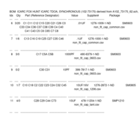
Example Transmitter Time Synchronization Checklist
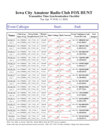
The
Event Validation Codes and the
IDs will change (7th. column),
but it shows all of the transmitters we will be using
and their operating frequencies.
This master list shows hardware and software information for these transmitters.
The battery state is recorded (by the
fox_clock utility) the evening before the hunt
as the TOY clock is updated.
Only the hunt organizer(s) will have access to the current sheet prior to the hunt.
Sample Transmitter Event Label

This is the label placed on the transmitter just prior to the hunt.
The
Event Validation Code and the
ID match up with the
Transmitter Time Synchronization Checklist shown above.
The transmitter should be oriented such that you can see the label
without disturbing the transmitter. 😇
Example Transmitter Receipt

There will be a stack of
Transmitter Receipts rubber-banded to each transmitter.
Please take one to validate your find and turn it in at the end.
Should there be no more cards, simply record the
Event Validation Code
and the
ID from the transmitter to validate your find.
There is space on the transmitter receipt to record your callsign and the
approximate time you found the transmitter.
Keep in mind that the
Event Validation Code and
ID are
generated prior to the event when the TOY clocks in the transmitters are
updated.
The newly generated transmitter labels and receipts (with updated codes) are printed at that time.
The values shown in the examples here are already out-of-date. 😎
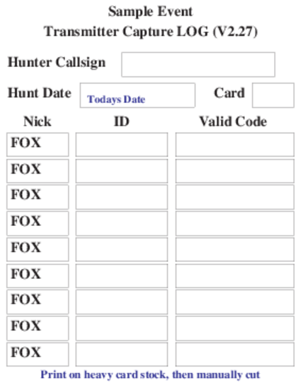
Sample Hunter Log Card

This is the log card for the hunter.
Should the stash of
Transmitter Receipts be used up,
the hunter can simply record the
ID and
Validation Code
on his log sheet.
The
Fox Hunt will start at 10:00.
You may also contact KC0JFQ at any time using this crude email obfuscator:
Sorry, but you need Javascript on to email me (or at
least expose the email address).
and let me know your schedule and venue preferences.
Back to the Top
Fox Hunting Hardware
Some projects that you may be interested appear below.
Circuit boards are on hand and for all of these and you may
send an email message to the email link above if interrested.
Don't miss the blue button on the right at the top in the
navigation bar. This links to more details for the ICARC
fox projects.
Back to the Top
These are local ICARC projects.
Back to the Top
Switched Attenuator
There are circuit boards available for this project!
A simple attenuator to insert between your antennas and receiver.
This uses the smaller Hammond enclosure, that is the same one used
by the
DTOA Switch and the
NVARC RF Detector.
The switches are low-cost slide type thru-hole mount. Resistors are all surface mount to limit cost.
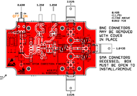
The antenna connections may be populated with SMA, SMB, or BNC connectors.
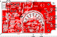
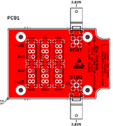 PWA
PWA
 Schematic
 MBR
MBR
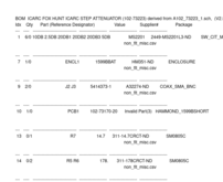 BOM
BOM
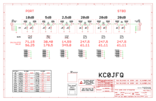
The two antenna connectors are positioned matching the
DTOA Switch to
allow reuse of an existing housing or to simply reuse the drilling jig.
The switch labeling is suggestive as all of the switch positions are identical.
You may, should you be so inclined, populate the three 20dB positions with
parts for 10dB (for a total attenuation of 47.5dB) or any other combination you
find convenient.
Back to the Top
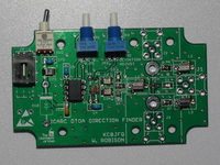
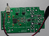
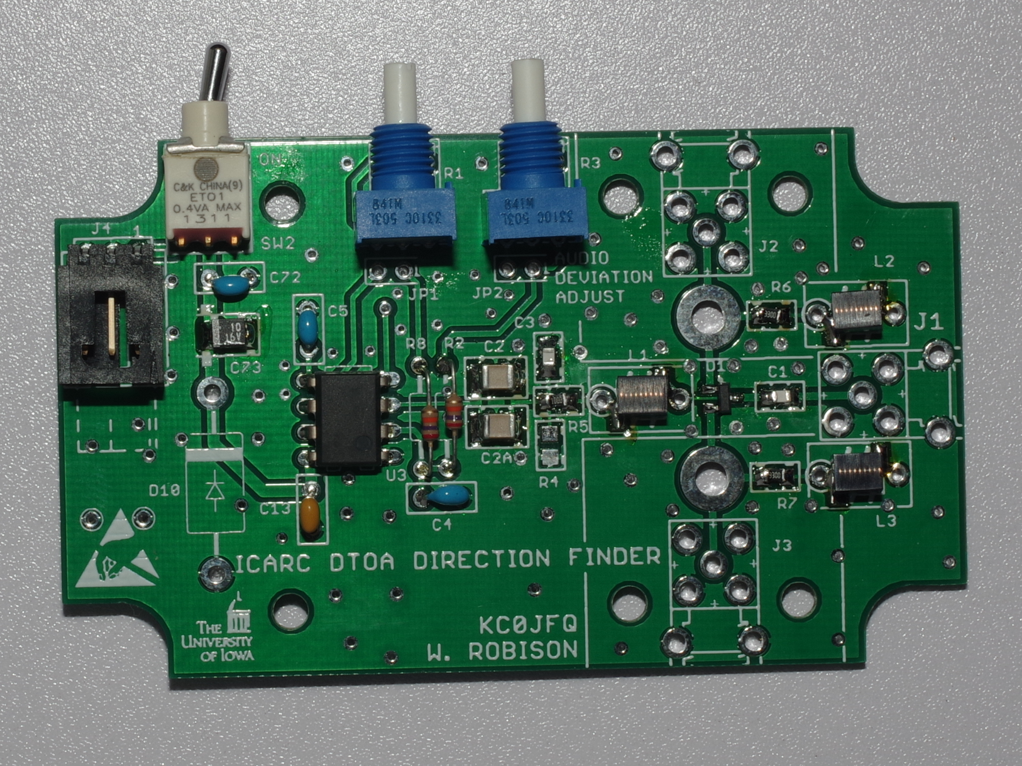
DTOA Switch
There are circuit boards available for this project!
The first project is a direction finding assist.
The DTOA acronym is "Differential Time of Arrival".
The DTOA switch is connected between a pair of
antennas and a handheld receiver.
When the antennas are normal to the transmitter (i.e. electrically equidistant)
the receiver doesn't notice the DTOA switch. As the antennas turn
away from the transmitter, a squeal is introduced into the audio.
 DTOA switch Schematic
Antenna End Schematic
DTOA switch Parts List (web page)
DTOA switch Master Build Record
DTOA switch DigiKey order spreadsheet
DTOA switch Schematic
Antenna End Schematic
DTOA switch Parts List (web page)
DTOA switch Master Build Record
DTOA switch DigiKey order spreadsheet
This file can be dropped directly into the
DigiKey ordering system
KC0JFQ Pages for this project
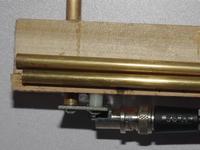
The last images in the group show the base of the prototype antenna.
The antenna is semi-rigid (hobby store) brass tubing.
The main part of the vertical element slips into the fixed
tube mounted to the base.
The long antenna elements are stowed for transport in this image.
Click the image to get to view a high resolution image.
The two antennas are mounted on a yardstick about
1⁄
2
wavelength apart, although this spacing is
not particularly critical.
The fixed portion of the antenna has a brass spacer that is tapped 4-40 solderd
at the base to provide secure attachment, this being visible in the image.
The coax connector in this image is a BNC, but an SMA connector may be substituted (SMA part numbers follow).
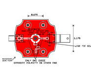
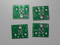
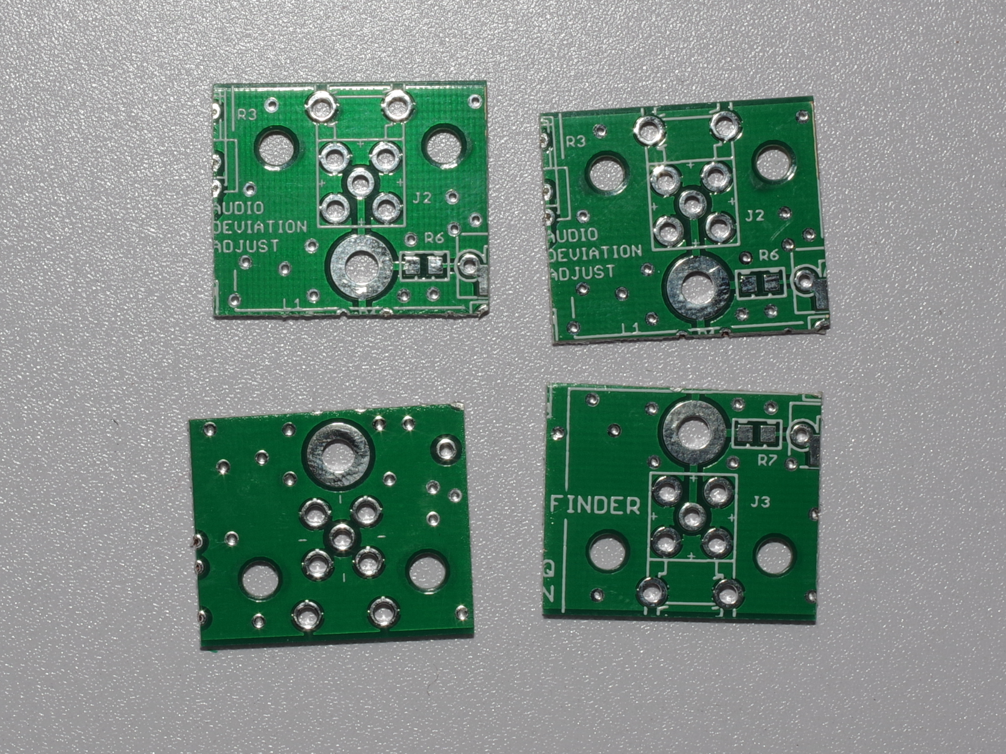
The connection from antenna base to the coax, shown in the far right image,
is cut from the main circuit board (that is two circuit boards are nominally required).
You see on the trimmed coax boards that a 0.125" hole is provided to attach
the antenna base. Either a BNC or an SMA may then be attached (SMA part numbers follow).
The two non-plated holes provide for mechanical attachemnt.
In our prototype #4 pan head sheet metal screws along with some short nylon
spacers are used.
A short piece of 1" stock is glued to the inter-antenna spacer
(i.e. the two yardsticks glued together) to provide a bit of support for
the antenna base.
The circuit board is used as a drill guide to set the holes before
being assembled to the antenna and the spacers.
The two nylon spacers are present only to provide clearance for the solder
joints on the circuit board.
The antenna in the image has not been trimmed to resonance. There has been
no effort expended in trying to achieve an impedance match.
A simple telescoping whip antenna should work equally well and
probably be less expensive than the brass tubing used for the
prototype.
Antenna spacing is also not particularly critical. The prototype
antennas are mounted on a garden variety yardstick from the local hardware
store with a spacing of 34 inches (1 inch from each end).
Misc. Substitute Parts SMA
J1, J2, and J3 on the 102-73170-A board may be populated with SMA connectors, if desired:
Right angle SMA Connector
Another Right angle SMA Connector
18 inch SMA Cable
24 inch SMA Cable
Misc. Substitute Parts BNC
Here are various BNC parts you may find useful:
Right angle BNC Connector (from parts list)
BNC to SMA Cable 18 inch
BNC to SMA Cable 24 inch
BNC Cable 18 inch
BNC Cable 24 inch
SMA to BNC Adapt
SMA to BNC Adapt
Misc. Parts
Here are some parts for the antrenna element termination boards:
0.125(ID)x0.188(OD) by 0.100 (Hgt)
0.125(ID)x0.188(OD) by 0.200 (Hgt)
0.125(ID)x0.188(OD) by 0.250 (Hgt)
Round Standoff, 4-40, BRASS, 0.250 dia. 0.625 long
Misc. Parts, Antenna
K&S brass tubing (0.014 wall) for antenna elements:
8132 9/32 brass tubing K&S, 0.281 dia. 12 inch
1149 1/4 brass tubing K&S, 0.250 dia. 36 inch
0.250 OD tubing requires working the threaded spacer diameter to fit!
8131 1/4 brass tubing K&S, 0.250 dia. 12 inch
1148 7/32 brass tubing K&S, 0.218 dia. 36 inch
Operation
Connect the switch to the receiver antenna input.
With power off, the receiver will act normally.
If you have mounted the antenna elements 1⁄2
wavelength apart, the receiver will null with the elements
lined up with the signal.
That is to say, when the DTOA switch is not powered, and the element spacing is
close to 1/2 wavelegth, the combined signal from the two antenna
elements will destructively combine thereby reducing the signal
seen by the receiver.
Once switched on, the receiver will receive normally when
the antenna elements are normal to the signal.
Your line-of-position is perpendicular
to the line between the two antenna elements (i.e. normal).
As you sweep your line-of-position away from the source, a squeal will be introduced and
be heard in the received audio.
The pitch is fixed by R2/R8 but the volume increases as the phase
change, introduced by the DTOA switch, increases as the antenna
elements differential distance to the source increases.
The system is sensitive to reflections, much more so
than a single antenna.
As you move further away from the transmitter you may see reflections
that have signal strength similar to the transmitter.
In an area with metal structures, power lines, equipment cabinets, power lines,
anything that will reflect the carrier, a false line-of-position
is easy to encounter.
Swing the antenna array back and forth to find the point where the
squeal introduced by the switch is minimized.
As you get closer to the transmitter this will be more pronounced.
Keep in mind that the line-of-position has
front-to-back ambiguity, so you need several lines-of-position
to establish the direction of the transmitter.
Consider: after establishing your first line-of-position,
move some distance perpendicular to that line and take another
line-of-position to start to resolve the front-to-back ambiguity.
When used with low power transmitters you may see the effect your
body has on reception, the front-to-back sensitivity may change.
You will still see the null if you turn around, but it will sound
slightly different.
You can also simply power off the DTOA switch and use the null off
the end of the antenna array to establish your line-of-position.
Once you establish the general direction of the fox transmitter,
you can sweep and walk to find the transmitter.
Back to the Top
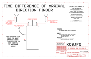
Synchronous DTOA
Yet another project (this seems to go on forever..)...
Boards are on-hand, but software development stalled for a bit :-(
This design is lifted from KA7OEI.
We use the carry-out of a decade counter to drive the antenna switch
and then look for the disturbance in the audio at the two
switching edges.
 PWA
PWA
 Schematic
 MBR
MBR
 BOM
BOM
Schematic:
Sheet 1:
General layout of the connections to radio and antenna.
Sheet 2:
CD4017 is the decade counter.
The CARRY OUT pin is a square wave, exactly what we need for
driving the antenna switch.
We choose two of the ten remaining outputs to sample the audio
stream from the radio, at the point where audio from the
radio shows the distrubance from the antenna switch.
Signal Conditioning
U4 and U7 gate the audio on to the sampling capacitors
C51 and C61.
U6$1 is configured as a differential amplifier to detect the
level of the antenna switching, i.e. the direction.
U6$2 is the meter gain control.
Timing Diagram
Signals on the CD4017 output pins and what the audio
from the radio is expected to look like.
Sheet 3:
The antenna switch
This is take directly from earlier designs.
A CMOS (not 74HC logic!) buffer drivers the PIN diode switch.
Sheet 4:
The
meter.
Here we use a processor to implement the meter function.
U9$B samples the analog values at 5 points in the system.
The software is more-or-less free to choose the analog channels that
will implement the meter function.
U9$C is the meter needle, that is the direction indicator
in the form of a line of LEDs.
U9$A has the middle LED, so our meter looks pretty.
Debugging
We have a serial port to aid in debugging the software.
Timing Control
The RESET and CLOCK signals allows the software to
drive the system an a software determined rate.
Processor Misc.
U9$0 is power, processor clock, and debug interface.
Back to the Top
Back to the Top
Back to the Top
ICARC Fox Hunting Infrastructure: Transmitters
We have a growing collection of transmitters that
are used for our fox hunting events.
Follwing the initial purchase of 3 low power
transmitters, KC0JFQ started a project to build
a more capable transmitter.
The trasnmitters in use are detailed below.
WB6EYV MicroHunt Foxhunting Transmitter
ICARC owns 3 of these units
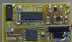 WB6EYV 50mW transmitter.
This uses the
Integtated Device Technology
(now
Renesas Electronics America)
ICS525R-02 to generate the RF carrier.
The PLL frequency multiplication is fixed with traces in the artwork.
Back to the Top
ICARC/KC0JFQ transmitters
There are two basic systems described below,
one being a low power unit and a second that
uses a Raspberry-PI as a control element.
The first design, the
zNEO SOC based units, was concieved
to provide an easily programmable FOX that can be deployed
in the field by simply turning the unit on as it is placed
in its hiding place.
Low power was also a consideration in the design.
The second design was an outgrowth of someone casually remarking
that is should be able to talk.
The ubiquitous line of Raspberry-PI computers provides a
convenient and cost-effective solution for this.
The downside of the Raspberry-PI being that is is not
designed to be power efficient.
In spite of the power hungry nature of the Raspberry-PI,
it is capable of operating on battery power for about 8 hours.
After some development effort, a means of producintg audio was
developed for the zNEO based unit. Although the zNEO can
now produce audio, it does require external software support to
generate and convert normal audio files into the low bandwidth,
limited resolution, file required to meet the limits
imposed by the 20MHz speed of the zNEO processor.
ZiLog zNEO SOC -7
ZiLog zNEO SOC -12
ZiLog zNEO SOC -25
ZiLog zNEO SOC SI5351
Raspberry-PI Zero
60mW Class D Amplifier
90mW Class D Amplifier
50mW Class C Amplifier
500mW walkie talkie module
Back to the Top
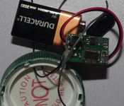
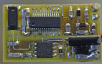
102-73161-7 ZiLog zNEO SOC
1 unit produced, this is the
proof-of-concept, the first one.
The prototype board.
A few haywires required to deal with missing parts.
The ICARC fox transmitter project started in early 2019.
Using the same ICS525R-02 to generate a carrier,
it produces about 1mW through the low power RF section.
Ther zNEO drives the control pins on the ICS525R-02 to
allow dynamic frequency selection. The frequency may change
at any time, includeing in the middle of a message.
Back to the Top Back to Transmitters
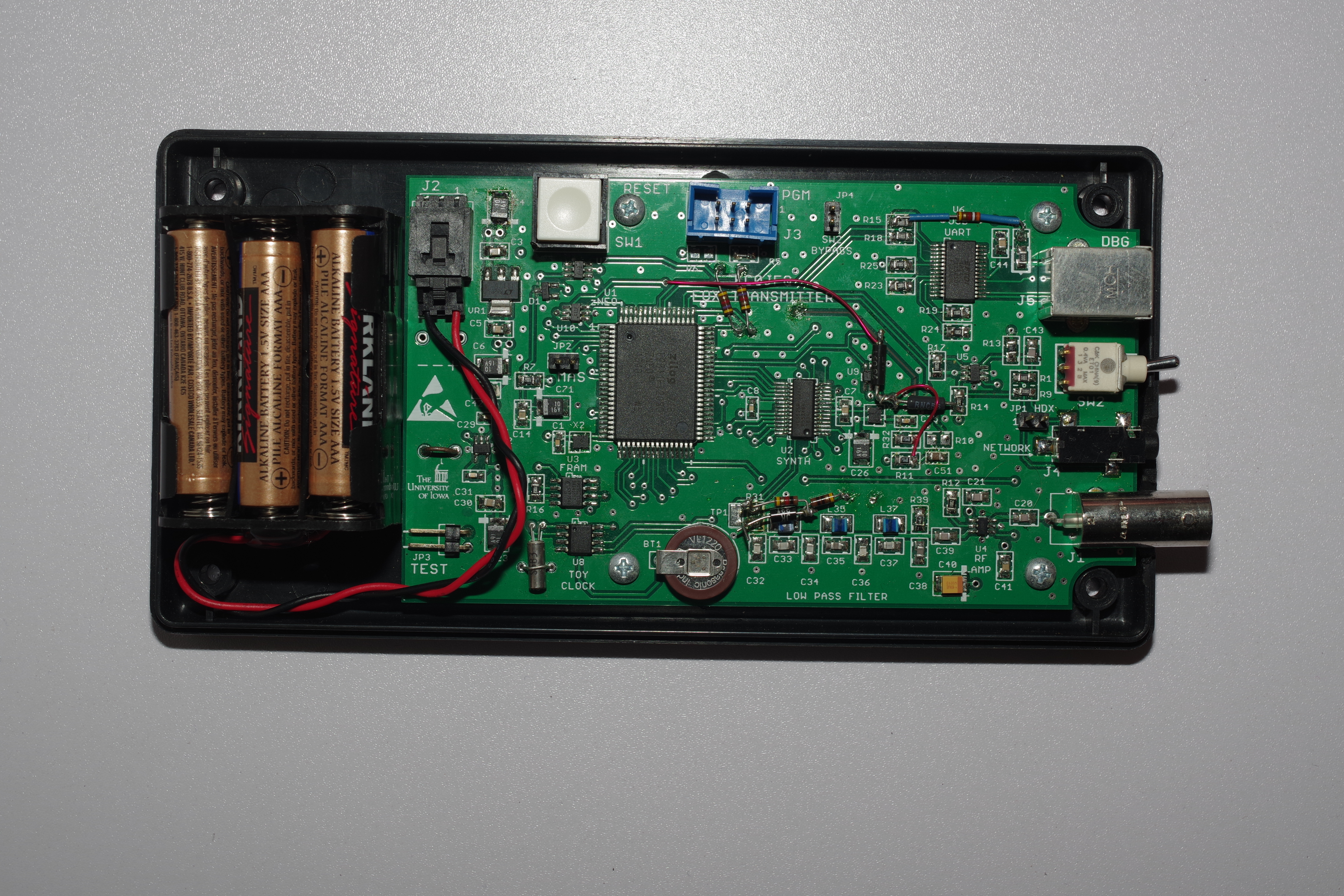
102-73161-12 ZiLog zNEO SOC
3 units
First Revision.
This revision adds the missing missing parts from the -7 board, above.
The RF section was changed in an attempt to
improve RF amplifier performance.
Mechanical changes on the board moves the network jack to make
room for a charging jack.
A 10 pin connector (not populated on this board) is added to allow the board to control
an external tranceiver.
A battery voltage monitor allows the unit to transmit its battery condition.
Bare boards and build documents are available for this revision of the project.
Back to the Top Back to Transmitters
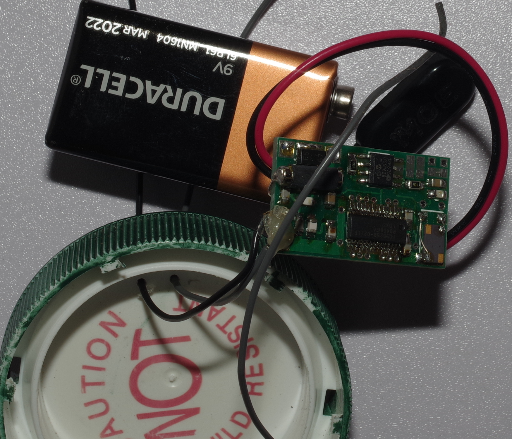
102-73161-25 ZiLog zNEO SOC
4 units
Second Revision.
This revision slightly improves the fit in the case while
remaining mechanically compatible with the -12 revision.
This major update for this revision moves the RF amplifier to a daughterboard.
The modulation control circuit is changed to allow the use of inexpensive
crystals rather than a VCMO.
The zNEO SOC also switches to using a crystal to reduce cost.
The first stage regulator changes to a switch-mode device to
improve battery life (run time is ow in excess of 24 hours).
The ICS525R-02 can now be powered from the 5V rail to increase
the
barefoot output power to around 30mW.
You can see the RF daughterboard shown has no active parts.
After some careful deliberation, I have managed to find a
means of processing audio clips.
Upgrading the FRAM to a 4Mb
device allows space for about 100 seconds of audio.
The existing units have room for 4 to 6 seconds of audio.
The audio clips are digitized at 4KHz so thet sound a bit muddy.
Although they need an FRAM upgrade, the callsign and unit name are
announced.
Sample voice output from this FOX:
Bare boards are available for this revision of the project.
Back to the Top Back to Transmitters
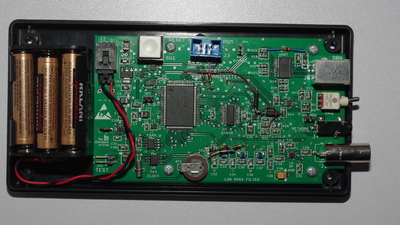
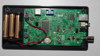
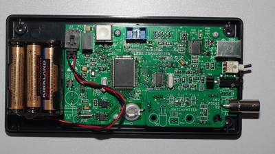
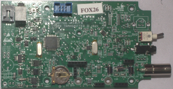
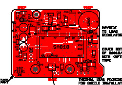
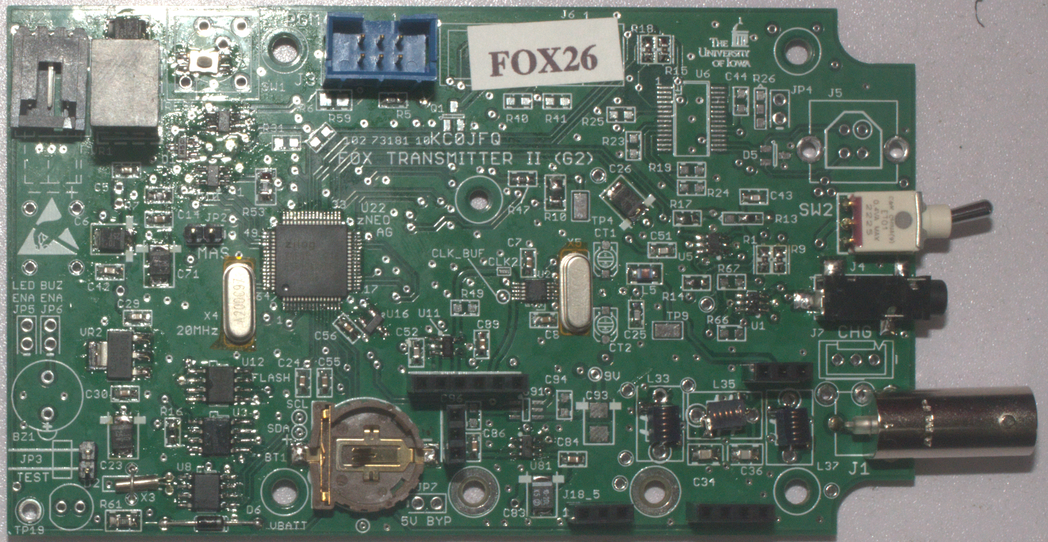
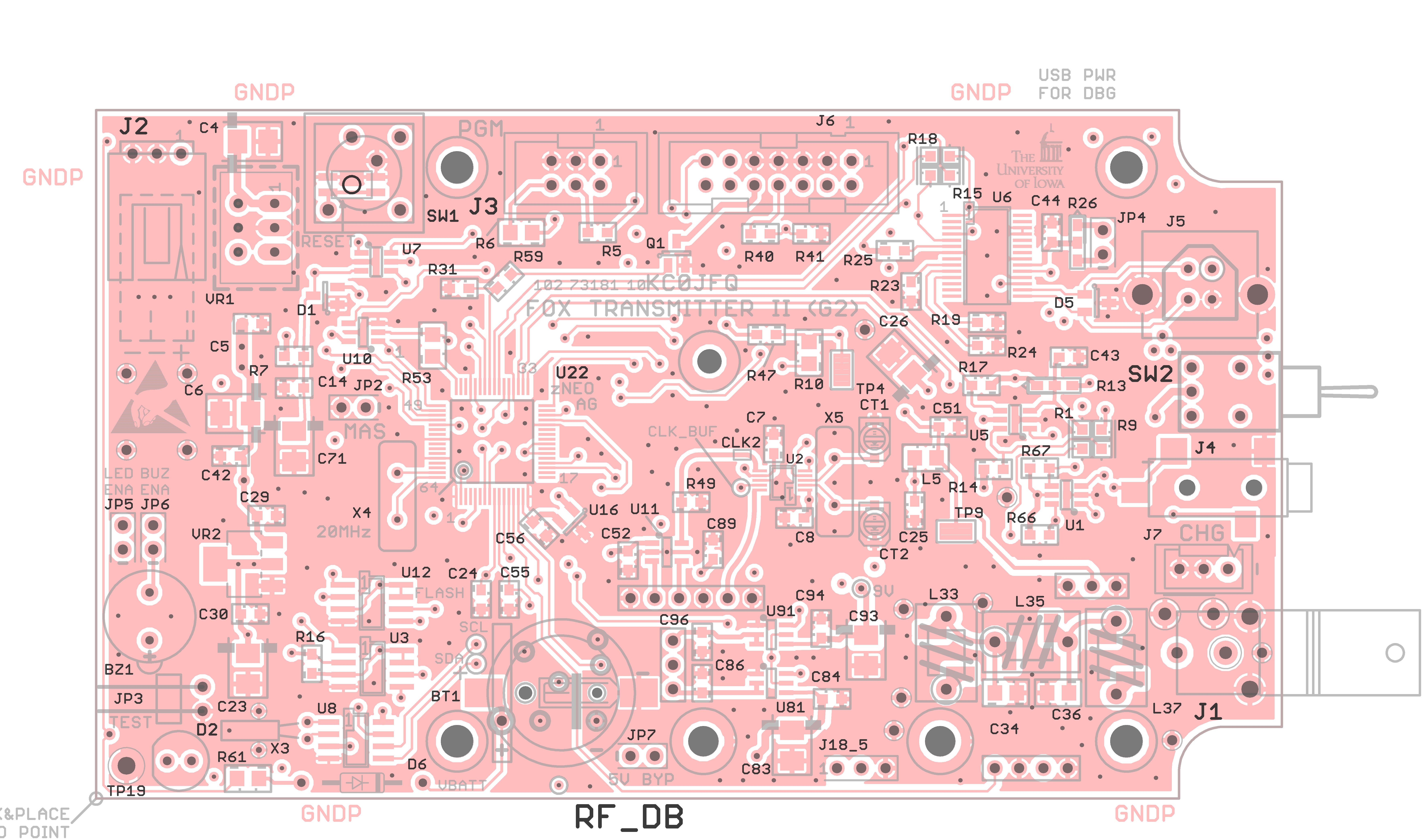
102-73181-10 ZNEO SI5351
We have 17 of these units that are operational!
Add to that five older (102-73161-25/102-73181-5) units.
We now have a large
skulk of transmitters.
The PWM audio channel that was
haywired on the 102-73161-25 board
to provide proof-of-concept.
It workes as expected and is now incorporated into newer versions with all the other
features of the 102-73161-25 board retained.
We have also incorporated the current sense from the 102-73176 board.
The external radio connector provides audio, PTT, and
a serial interface for controlling an external handie-talkie.
Also present on the connector are two analog channels;
a switch channel and a CdS photocell channel (from the 102-73176-0 design).
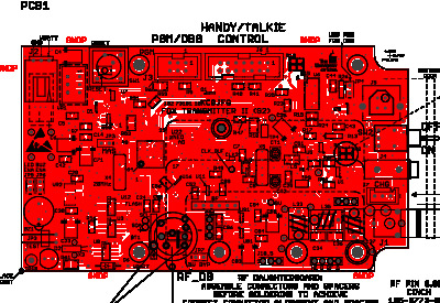
The circuit board remains mechanically compatible with the
102-73161 boards. The pinout of the handie-talkie connector
is a superset of the 102-73161-25 design (pin allocations align
to keep mechanical compatibility).
The 102-73181 design is provisioned with 2 memory devices,
one being a smaller FRAM which is easy to alter manually
(as it doesn't require sector/device erase)
and a large Flash device that is used to store audio waveform data.
The FRAM installed on the board is typically a 256Kb device
(we aren't restricted to what appears in the parts list).
The FLASH device installed will ususally be an 8Mb
or larger device.
Also added to the design is a means of keeping the clock
battery fully charged when the main battery is connected.
The host interface is changed over to a 3.5mm connector,
similar to an ICOM CI-V interface.
The connector is physically a TRS type to allow for full duplex operation.
The newtork time feature of the older boards is deprecated
to support the DRA818 module.
This design uses much less power than the 102-73176
(Raspberry-PI) design, while keeping the ability to speak.
Startup time is the same as the 102-73161 units as it uses similar
software. It is ready to transmit in just a few seconds, so a unit
alive message can be broadcast almost immediately following power on.
This design also adds an additional connection to the daughterboard
interface in order to route the
second serial channel (what was the time network on the 102-73161 boards) to the allow control of the
SA818/DRA818 tranceiver module.
Loading FRAM/FLASH
Both FRAM and FLASH may be loaded through the command-line interface
(using the 3.5mm connector).
There is a command to save the
command line tail to FRAM (in the next available location).
The FLASH can be loaded using InTeL HEX records from the command line.
Both FRAM and FLASH must be cleared prior to loading new contents through
the command line interface.
The FRAM can be edited in place without erasing the entire device
(you can erase single records in FRAM).
The latest S/W version also provides for a high speed binary loader
that greatly speeds up loading of the memory devices.
FRAM is is simply overwritten using this method and does not require
that a clear operation prior to a reload.
The FLASH device must be manually cleared prior to loading
(some of the larger devices take many seconds to erase).
Once erased we simply run the binary loader against the InTeL HEX file
that would be passed through the command interface.
The binary loader returns to normal command-line mode at the end
of the loading process.
There is an expectation that you will load the audio waveform files
infrequently.
Using a large FLASH device allows audio for
an entire skulk of foxes (i.e. all the nicknames) to be present
in each transmitter (common audio file).
Back to the Top Back to Transmitters
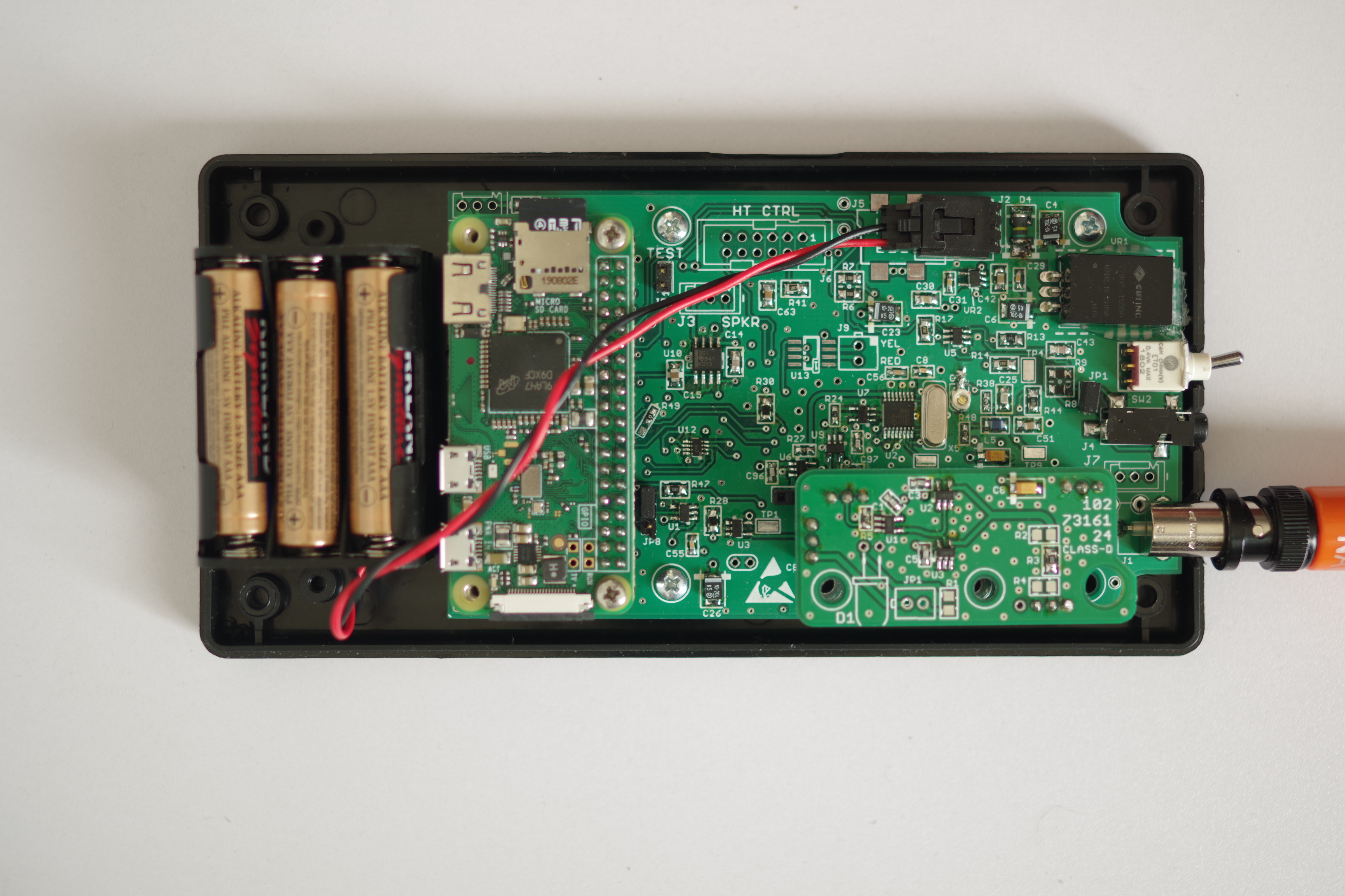
102-73176-0 Raspberry-PI Zero
Some wag asked if it could talk. Well now it can!
This design makes use of a Raspberry-PI running Linux.
3 units
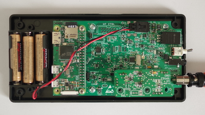
Raspberry PI Zero-W.
2 major changes to the system:
- Change ZiLog zNEO SOC to Raspberry PI Zero.
- Change from ICS525 to ICS307 (ICS525R-02 is an end-of-life part).
Keeps the same mechanical interface to the enclosure as the 102-73161-25.
Modulation control voltage comes from a PWM channel
in the Raspberry PI that is configured as an audio DAC (i.e. a sound card).
A class-D amplifier daughterboard is mounterd in the above picture.
It makes use of a pair of 74LVC04 buffers which produce about 60mW.
Operating
barefoot will produce about 30mW.
A battery current monitor was also added to allow battery power monitoring
and analysis.
An audio amplifier drives an on-board speaker for debugging
and to allow the unit to
talk.
The
Raspberry PI Zero W is a power pig!
Run time on six "AAA" batteries is about 8 hours, so fresh batteries
are generally required for each hunt.
The
Raspberry PI Zero, lacking WiFi capability,
is mechanically and electrically compatible.
The WiFi on the
Raspberry PI Zero W provides a convenient way to
access the unit to download software and .wav files.
Sample voice output from this FOX:
Sample CW output from this FOX:
Bare boards and build documents are available for this project.
Back to the Top Back to Transmitters
ICARC/KC0JFQ Power Amplifiers
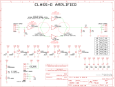
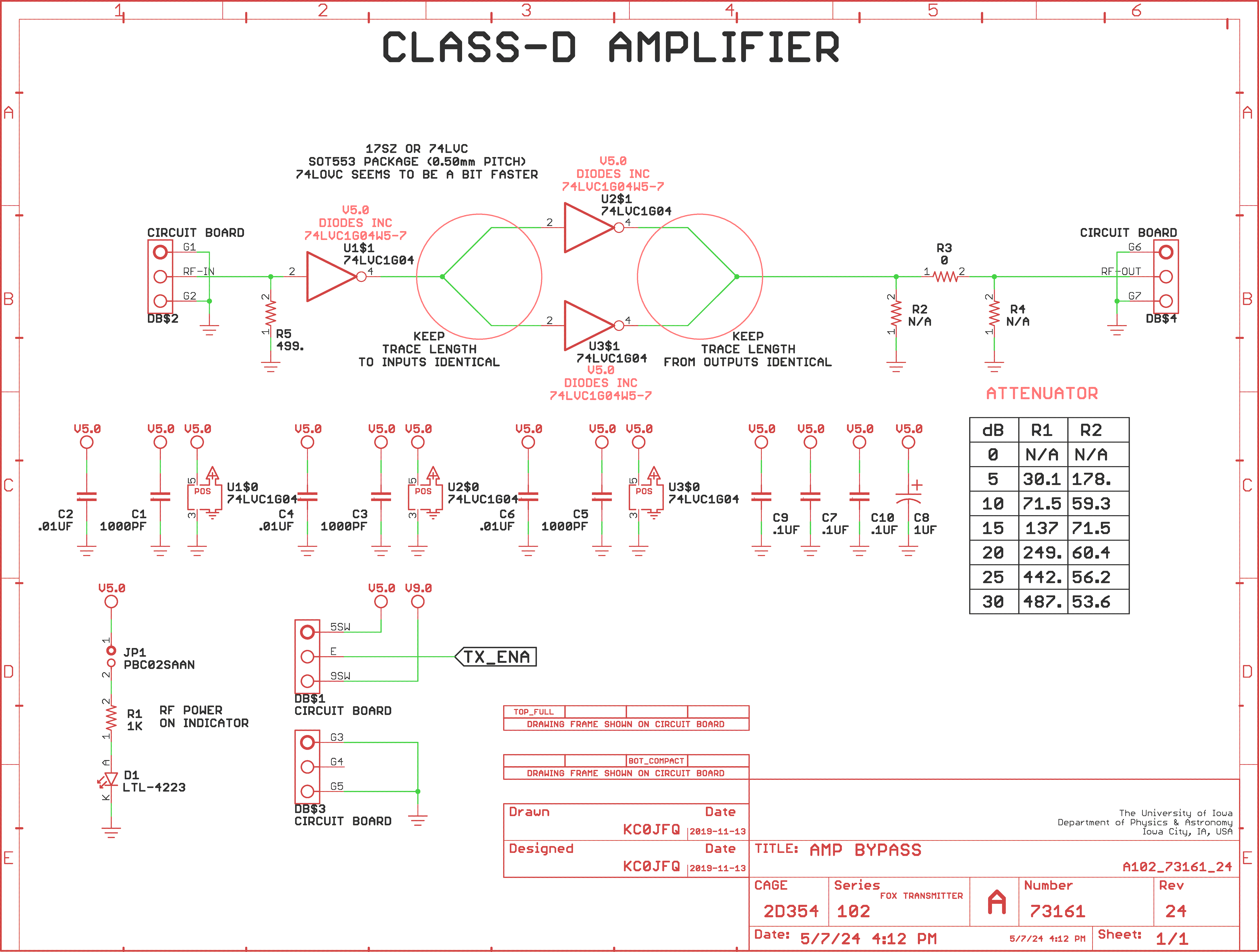
102-73161-24 60mW Class D Amplifier
Class-D Amplifier
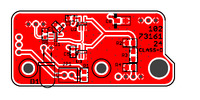
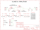
This is a trivial Class-D amplifier that uses a
high speed low voltage CMOS inverter.
All three active devices are
74LVC1G04W5-7.
This specific device is chosen for its fast propogation.
U1 is an input buffer while U2 and U3 are the output drivers.
The 74LVC1G04 device is supplied by
Diodes Incorporated
boasting a 1.6nS propagation delay along with an output drive of
about 30mA.
At VHF frequencies the 74LVC1G04 is operating near its maximum
speed resulting in relatively slow rise and fall times.
Much of the high frequency content is attenuated by the device itself.
The output from the drivers is passed through a low-pass filter on the main
board and then on to the antenna.
R2,R3, and R4 provide a pi network to attenuate the signal should that ne
required. Nominally R3 is populated with a 0 Ohm resistor.
D1 is provided as a debug aid.
It is powered from the 5V rail that powers the 74LVC1G04.
D1/R1/JP1 would typically not be populated.
Back to the Top Back to Transmitters
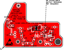
102-73161-27 90mW Class D Amplifier
Class-D Amplifier
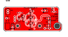
This is a 3 gate implementation of the
Class-D amplifier design.
RF traces are all rounded and trace length
into and out of the gates are matched.
This is on a 4-layer board.
Three layers are ground and one is power.
Back to the Top Back to Transmitters
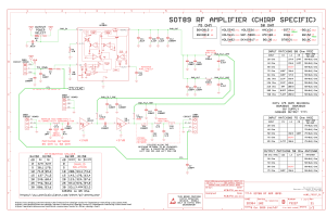
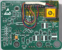
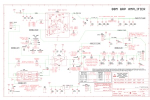
102-73181-28 50mW/100mW Chirp Amplifier
Class-C Amplifier
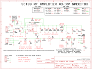
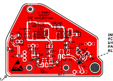
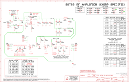
With Schematics
This is also an MMIC implementation of a
Class-C amplifier.
Added is a power switch to allow convenient implementation
of a chirping system.
Not real radar chirping, rather chirping like a bird.
A simulation of the operation of a wildlife tracker.
If you have a look at the 102-73181-36 walkie talkie module,
this implements the PTT function in the same way.
Back to the Top Back to Transmitters
102-73181-36 500mW or 1000mW walkie talkie module
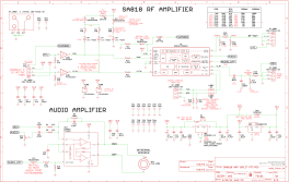
This amplifier daughterboard makes use of either an VHF
module (SA818V, DRA818V) or a UHF module (SA818U, DRA818U).
walkie-talkie module (sourced from China).
The 102-73181-101 board has the power control seperate from
the transmit enable on the daughterboard to accommodate the
timing requirements of the DRA818 module.
Earlier boards can not provide the timing necessary to
reliably control the RF module so are not supported.
Output power is controlled by a jumper on the daughterboard.
This RF module provides a fixed output power of between 75mW and
750mW (the output power seems to vary a bit between modules).
For our Fox Hunt application, the audio amplifier in never populated.
Although the SA818/DRA818 module supports receive operation,
the operating software removes power from the daughterboard
between messages to conserve power.
The audio amplifier section is provided only as a software debug aid.
Back to the Top Back to Transmitters
Latest RF Amplifiers
102-73227-21 150mW VHF Amplifier
Prototype VHF Amplifier with GPS Module

This is the cascaded MMIC amplifier design with additional
support for adding a GPS Module.
This RF board is a super-set of previous VHF modules.
A soft-start feature is included on this board that ramps
up the voltage on the board as it is switched on.
102-73227-15 750mW HF Amplifier
Prototype HF Amplifier with GPS Module
This is a simple Class-C amplifier for operation in the 80M band.
As we do not want to have to alter parts on the main board, the Low-Pass-Filter
for 80M appears on this board. The 2M LPF remains on the main board.
Using the Fox Transmitter on 80M becomes a simple swap of the RF board
and attaching an antenna tuned for the 80M band.
The same soft-start feature used on the 102-73227-21 board is included
on this board.
We operate CW on 80M as the RF section doesn't do SSB (only FM).
The soft-start feature eliminates some of the key-down harshness.
Back to the Top Back to Transmitters
Fox Hunting Transmitter Software
Here is the operating manual for the version 4.20 software.
This is a sample configuration file that is loaded into
one of the KC0JFQ fox transmitters.
These are the commands that configure and control the operation of the
transmitter.
They may be loaded into the transmitter through the USB/serial
interface using a simple terminal emulator (i.e. no special
control software or USB drivers are required).
In practice, KC0JFQ uses a binary loader to considerably speed up the
process.
Audio files for the zNEO system are gathered together into
an Intel HEX file for download into the transmitters FLASH.
The audio directory records are located in FRAM
after the configuration commands.
The hex file processing in the zNEO tolerates the extra whitespace
that makes the Intel HEX Record a bit easier to read.
Extended addressing is managed using a type-4 extended address record.
The type-2 and type-3 records are ignored and must not be used in the audio
load image.
Back to the Top
ICARC/KC0JFQ Baofeng UV-5R Receiver Setup
Setup for the
Dirt Cheap Baofeng UV-5R Receiver
Using
CHIRP to program the
unit.
The radio is programmed using a modified
ICOM CI-V Interface
(
102-73226-3/
102-73226-62)
Operating
Frequency |
Group
Name |
Additional Information |
|
| 144.150 MHz
| SIGNON
| Fox-Hunt Setup Frequency
|
| 144.225 MHz |
FX21-26
| Six unit transmitter group
|
| 144.325 MHz |
FX27-32
| Six unit transmitter group
|
| 144.250 MHz |
FX33-38
| Six unit transmitter group
|
| 144.285 MHz |
FX5-8
| 102-73161-25 group (not in use)
|
| 144.305 MHz |
FX1-4
| 102-73161-12 group (not in use)
|
| 147.150 MHz |
K0GH
| Iowa City Repeater
|
| 146.520 MHz |
CALL
| CAlling Frequency
|
The UV-5R is programmed with
transmit inhibits
in place to allow the unit to be handed out without
worrying about the user keying the transmitter.
They can be ordered through Amazon.
If you want it programmed, KC0JFQ as the hardware to accomplish this task.
Back to the Top
Links on the KC0JFQ FOX wep page for search engines to stumble into
Fox Hunting
Fox Transmitter
Amateur ARDF
Fox Hunting
ICARC FOX HUNT
Next Fox Hunt
DTOA Switch
Raspberry PI FOX Transmitter
FOX_PI Features
FOX Transmitter
Features
Description
Board Status
Software Status

Last verified 19 Jan 2021, email obfuscator incompatible!


 This is a trivial Class-D amplifier that uses a
high speed low voltage CMOS inverter.
This is a trivial Class-D amplifier that uses a
high speed low voltage CMOS inverter.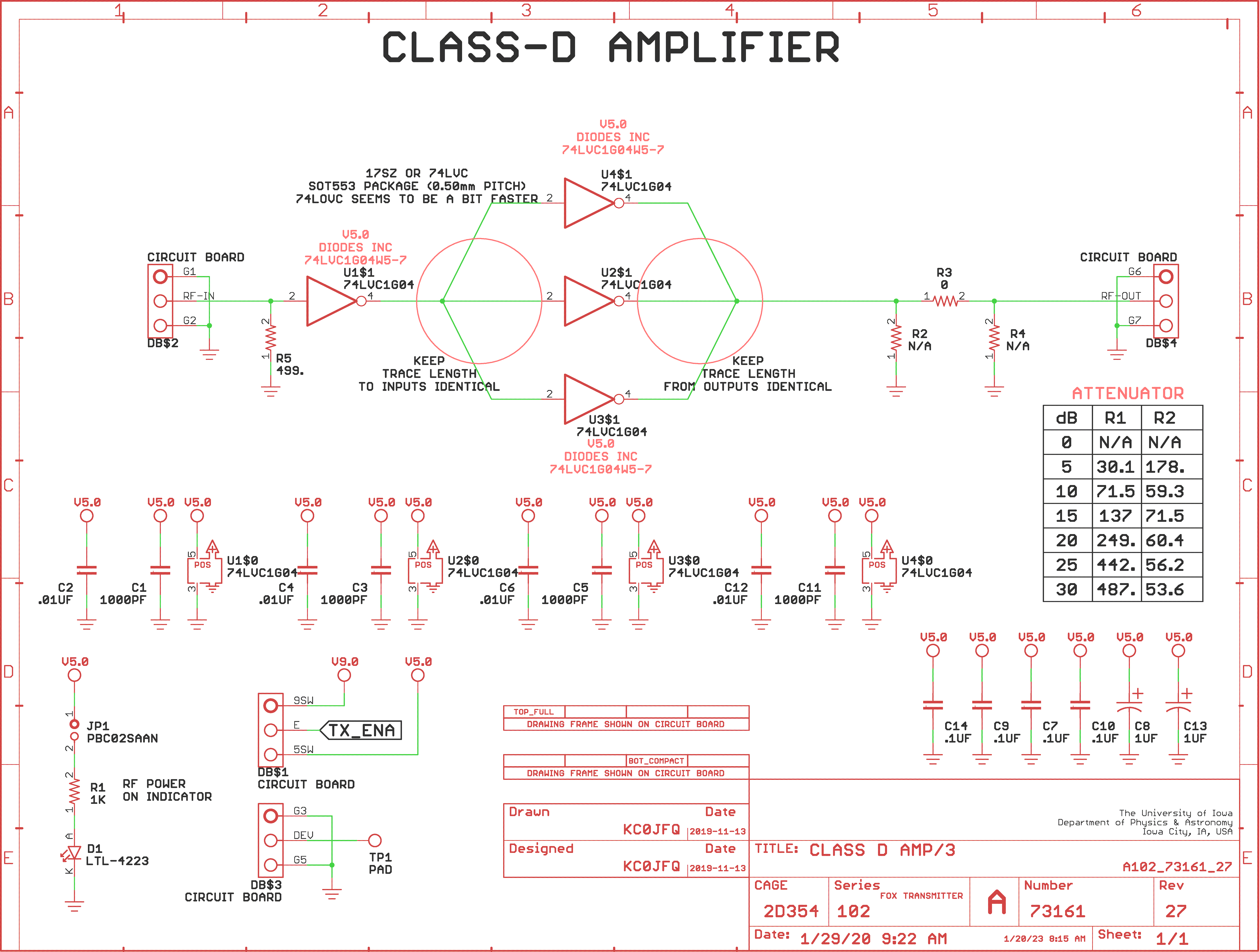
 With Schematics