ICARC Logo in World Map


Information about HAM Radio Direction Finding projects


Presentations and ARRL Article files

QST Article: FOX_ARRL.pdf
File Manifst: FOX_ARRL.lst.txt
Compressed TAR Archive of the QST Article
Engineering File Summary
ICARC FOX zNEO System Users Manual
ICARC FOX zNEO System Presentation Slides
ICARC FOX zNEO Hardware Presentation Slides
ICARC FOX RX DTOA System Users Manual
ICARC DTOA Antenna Switch Manual

102-73161/102-73181 Software images

102-73161 and 102-73181 Software images (Intel HEX file)
Software
Version
Notes & Comments
3.76
19 Nov 2024

-1KHz ext tab
-2KHz ext tab
-3KHz ext tab
-4KHz ext tab
-5KHz ext tab
-6KHz ext tab
-7KHz ext tab
-8KHz ext tab
-9KHz ext tab
-10KHz ext tab
-11KHz ext tab
-12KHz ext tab
-13KHz ext tab
-14KHz ext tab
-15KHz ext tab
-16KHz ext tab
-17KHz ext tab
-18KHz ext tab
-19KHz ext tab

Audio Waveform
Updates:


cmd_time V1.05
        TIME command sets sub-seconds...
            makes CHRP easier to overlap...
3.75
03 Nov 2024
Updates:

cmd_message V1.11
        move to synchronous scheduling for CHRP...
3.73
25 Jul 2024

Updates:


cmd_help V1.02
        clear uart_temp_buffer to ZERO before we start...

command V3.21
        add BATR command to provide battery capacity data

cmd_battery V1.07
        add BATR command to provide battery capacity data
        add 5V monitor to BATR command

batt_plot (external support utility)
        analyze BATR reports
3.72
09 Jul 2024
Updates:

        add FOFF command to track offset in external frequency table.
            Internal SI5351 freq. table has 0Hz offset
            Si5351 requires external table for proper operation
            CONF command adjust reference xtal capacitor
            Default SI5351 crystal load is now 8pF.
        Change control port default speed to 56K.
            H56K change to H115
        HERA now support block mode
        STAR command working
        Add interrupted carrier control bit
        T2 default time increased to 150mS


The audio data is provided as an example, you will need to generate your own file with appropriate callsigns.
You may simply build your callsign and nicknames and load them following the example table
(leaving status vocalizations unchanged).

You will also need one or more of the external frequency tables.
Measure the frequency error using the internal table,
then load the appropriate external table into FRAM.
Generate and load more table entries to extend operating frequencies.
3.63
11 May 2024
Updates:

        Fixed bug in CHRP command
        Fixed bug in MODC command
        Added devices to FLASH/FRAM table
        Added check to allow console exit from HEX dump
        Add 32 bit address support for FLASH device larger than 128Mb
        Disable ALL SI5351 clocks (CLK0..CLK7)
        Fixed RUN0 command string matching
3.54
23 Mar 2024
Updates:

        Audio sample rates 10K and 16K added
        Reworked how TEST and MAS jumpers are handled.
        102-73161-25 voltage coefficient selection fixed.
        Recalculated battery sense coefficients.
3.34
14 Mar 2024
Updates:

        Update for the 102-73181-10 boards.
        Compatible with 102-73161-25 and 102-73181-*
        DRA818/SA818 timing accommodations.
        SI5351 synthesizer.
        Expanded audio features (2nd. FLASH memory).


Back to the Top


ICARC FOX HUNT

      foxhunt @ n952 . ooguy . com

Next Fox Hunt

30 March 2024

F.W. Kent Park
Conservation Education Center. Parking lot N.E. corner

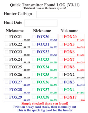
There will be six new 100mW+ KC0JFQ transmitters in use.
This new transmitter set is grouped together on the same frequency.
These will be located throughout the park, beyond walking distance.

Five of the older transmitters will operate on a second frequency.
These will be located around the CEC pavilion (i.e. within walking distance).

Finally, there will be a three transmitters that operate more-or-less continuously.
These three will, of course, all be on different frequencies.

Transmitter Operating Frequencies
  1.   144.225 MHz
  2.   144.285 MHz
  3.   144.305 MHz
  4.   144.335 MHz
  5.   144.565 MHz

This is the handout (an imaginary operating scenario, if you will) with a log sheet for the FW Kent Part hunt: ICARC_FOXHUNT_KP.pdf

Back to the Top


DTOA Switch

8 (EIGHT) 102-73170-A boards on hand!
Have ORDERED more! they are the 102-73170-20 (all surface mount) boards!
Also ORDERED the 102-73170-31 Antenna Base boards, lots of 'em.

ICARC DTOA Antenna Switch Manual

First working model showed up at the November 2022 hunts!
Results were very good!
On the 12-MAR meeting I had a tally of 11 units.
$$$ estimates will be worked on this week. It will be broken into several parts as the major cost is for connectors and cabling (roughly $75 when ordering from DigiKey for 3 built-up coax and 5 connectors). The boards themselves are much less expensive as they are mostly nickel & dime parts.

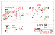
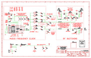
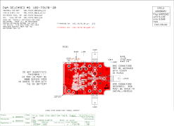
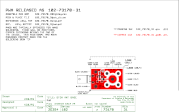
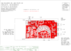
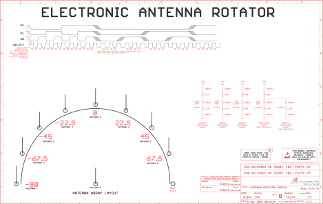
Schematic Image 102_73170_A (TLC555)   Schematic Image 102_73170_20 (CD4047)   Schematic Image 102_73170_31 (ANT)   Not-yet-rendered Image 102_73170_62 (CD4017)

"Differential Time of Arrival" switch schematics (the -A is what we're building in April).

The board we have on hand, 102-73170-A, can be built up in basic form for about $30.00 and it uses our old friend, the 555 timer, to generate a square wave at a convenient audio frequency to control antenna switching.
This switching signal signal is AC coupled through C2 to bias D1.
D1 is a PIN diode pair so one is forward biased and one is reverse biased.
Only the forward biased diode carries the RF signal through to the receiver.
This switching action is demodulated by the attached receiver.
When the antennas are at different distances from the transmitter the signal to the HT is phase modulated which appears as a howl at about 1KHz.
You should be able, then, to use the null to point at (or away from) the hidden transmitter.

The second schematic, 102-73170-20, switches to using a CD4047 which produces a square wave output without having to balance the circuit.
This artwork is entirely surface mount! (it manages to save a few cents on capacitors)
This revision also attempts to increase the isolation between the two antennas when operating by changing the topology slightly and adding a CD4049 buffer chip. This change increases the reverse bias on the PIN diode.
A order for 50)102-73170-20 boards and 100)102-73170-31 boards has been placed. Make one, make many; outfit the whole family! (102-73170-31).

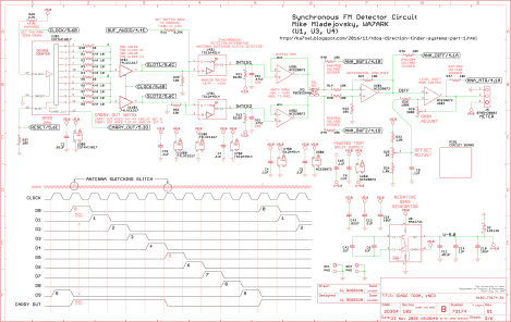
The fourth schematic, 102-73170-62, uses the same antenna switching scheme as the 102-73170-20 board and adds two interesting items. First a synchronous detector to pick out the audio glitches from the received audio. Second, a crude emulation of a panel meter using a set of LEDs to try to give the user an right/left indication of where the signal is...


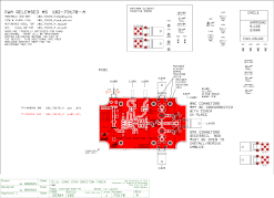
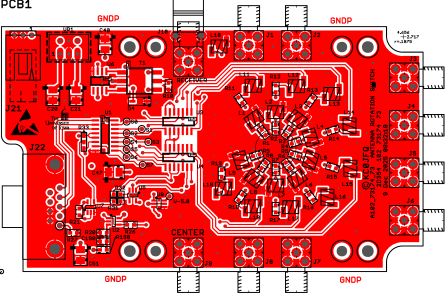
PNG Image 102_73170_A (TLC555)   PDF Image 102_73170_20 (CD4047)   Circuit Board Image 102_73170_31 (ANT)   Circuit Board Image 102_73170_62 (CD4017)

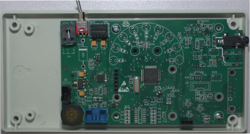
The circuit boards are the same outline used for the ICARC Fox Finder so it will be housed in the same Hammond plastic box.
The off/on switch position matches the ICARC Fox Finder but the coax connector is located in the exact center of the board to keep pathlength from the right/left antenna connectors the same.

Either SMA or BNC connectors may be installed on the board, we will install all SMA to reduce cost a bit. This also matches the antenna connector on todays hand-held trancievers.

The cables to the two antenna elements should be very close to the same length or the null direction will be affected.
We address this by simply purchasing pre-made cables (from DigiKey) although you certainly use or make yoour own cables.
The board is provisioned with three methods of adjusting the 555 timer frequency and duty cycle.
A simple one turn pot, a 10 turn pot, or a resistor.
The first prototype unit used a 10-turn pot to select the resistor values shown in the schematic for R2 and R8.
Production units eliminate the expensive adjustable pots and are not adjustable.
You certainly can install pots if you want to change the pitch of the squeal.

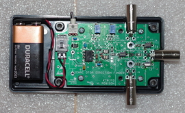
The far right panel is the latest DF hardware. Note the semicircular LED array that forms the meter emulation. For all this to fit, the enclosure is larger, being the same enclosure used for the FOX Transmitters. The board form-factor also matches the FOX Transmitter which allows for the use of AAA batteries for power.

Back to the Top


102-73170-A Documents

The current parts list webpage with links to DigiKey.
DigiKey Parts List (CSV) In this file the Item column numbers match the Index column number in the web page.
DigiKey Parts List (CSV) A slightly different format (use with DigiKey BOM manager)
        Specific parts in these lists may be unavailable or at a higher asking price,
        parts substitution may necessary in order to obtain parts.
        Substitutions may also be used to reduce price as long as you don't change package size.
The current master build record. This is a checklist for all the parts.

The current parts labels. This is labels for bagging parts.

Parts Price List
Parts Packing List

Back to the Top


102-73170-20 Documents


The current parts list webpage with links to DigiKey.
DigiKey Parts List (CSV) In this file the Item column numbers match the Index column number in the web page.
DigiKey Parts List (CSV) A slightly different format (use with DigiKey BOM manager)
The current master build record. This is a checklist for all the parts.
The current parts labels. This is labels for bagging parts.
Parts Price List  
Parts Packing List   PROD   PROTO  


102-73170-62 Documents


The current parts list webpage with links to DigiKey.
DigiKey Parts List (CSV) In this file the Item column numbers match the Index column number in the web page.
DigiKey Parts List (CSV) A slightly different format (use with DigiKey BOM manager)
The current master build record. This is a checklist for all the parts.
The current parts labels. This is labels for bagging parts.
Parts Price List  
Parts Packing List   PROD   PROTO  

Back to the Top


Datasheets

  Z8F1680 Datasheet  Z8 Encore! XP
  TLC555 Datasheet   CMOS Multivibrator
  CD4093 Datasheet   CMOS Quad NAND (Schmitt trigger)
  CD4050 Datasheet   CMOS Hex Buffer
  CD4049 Datasheet   CMOS Hex Buffer
  CD4047 Datasheet   CMOS Multivibrator
  CD4017 Datasheet   CMOS Decade Counter
  1SV267 Datasheet   PIN Diode
  BAR63 Datasheet    PIN Diode


The third schematic (i.e. the small one) is a prototype antenna element termination board. The schematic has a crude drawing of how to fab up the dual element antenna.

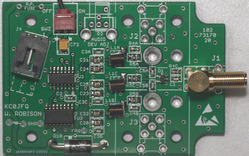
Board Image First prototype. Board Image Second prototype. Board Image Board Image Antenna Base.

The RF section of the prototype (-A board), on the right, is all surface mount
(everything to the right of C2/C2A on the schematic).
This is the Engineering Model on the left which used pots in the R1 and R3 positions to trim out the 555 timer.
Production boards eliminate the pots by simply putting the trimmed values in the R2 and R8 positions
(save purchasing expensive trim pots).
D18 is a reverse polarity protection diode.
Don't mess with the battery with the power switch on!

The Second revision (-20 boards) is all surface mount. The mounting hole layout exactly matches the -A board. You can see that the power switch on the -A board would be off the edge of the -20 board, the -20 board being smaller in the X dimension thanks to being all surface mount.

We will build both with fixed tone (i.e. fixed resistors setting the frequency) and only one SMA connector pointing toward the radio.
The battery connector will be soldered directly on to the circuit board, eliminating the connector and header labeled J4.
You are free, of course, to implement any of these features by installing the additional parts.

Hardware Image
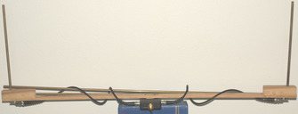
This is the prorotype that has appeared at all of the fox hunts for the last two years.

The connectors and cables to the antenna elements total up to about $50 and I believe we can simply replace them with two equal lengths of wire. This "hardwires" the board to the antennas.
The two antennas are brass tubing mounted to a pair of yardsticks glued together. The two smaller tubes are dismounted and telescope into the two vertical sections.

More cost savings can be had here by making use of parts you have on hand as the antenna elements are not particularly sophisticated. Click on the image here to go to the (much) larger image and you can make out the antenna base boards. These were made by cutting up one of the DTOA boards. The short antenna base tube has a round brass threaded spacer soldered into the bottom end where it fastend to the antenna base board (see the 102-73170-31 board).

The antenna elements themselves are not particularly critical. The prototype will DF a strong signal without the 36" extensions installed.
A pair of telescoping antennas can be found on amazon. These should work just like the prototype although I have no idea the diameter. The thread appears to be M3.


Back to the Top


zNEO FOX Transmitter

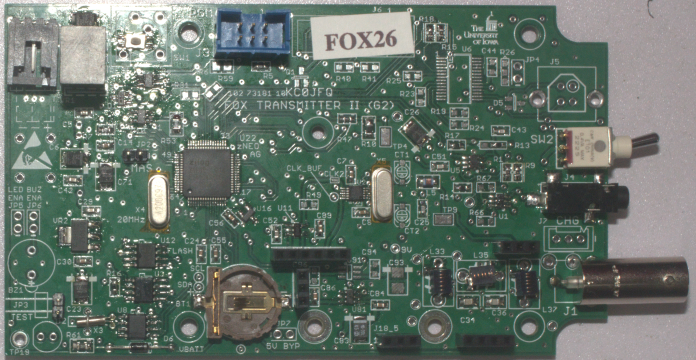
Circuit Board Image
102-73181-10 Board


102-73181 Features


Description

This is a programmable Fox Transmitter with large message storage. We are not limited to a very short message repeated over and over. Enough storage appears in the FRAM to have a 15 minute CW message!

New wildlife tracker emulation feature appears in recent software updates. The Fox Transmitter sends the normal ID message and then sends interrupted carrier.

The control processor is a ZiLog zNEO. The program memory in the zNEO is 128KB. This large program memory in the zNEO allows for a feature-rich control language and scheduling methodology.

In the 102-73161 transmitter, a single FRAM device holds configuration and audio data. A larger FRAM device may be installed to allow for longer audio clips.

The 102-73181 transmitter adds large FLASH device that is considerably less expensive compared to a similar sized FRAM device.

The 102-73181 transmitter continues to support a USB port; it is physically present on the circuit board but would not typically be populated. The serial port is moved to the 3.5mm jack that is accessible without opening the case. The network time function has been removed.


Field Prorgammable

There are no special tools required to load an operating sequence into the unit. An existing operating sequence may be erased using a simple command. Multiple messages may be stored in memory, even if they are not actively used.
The scheduling alogrithm allows simply coordination of multiple transmitters operating on the same frequency.

102-73161 Users Manual
102-73181 Users Manual

Command List

Sample signon report

Sample status report

Sample initialization commands
Sample announce commands

Sample S0 commands

RF Power

For the most part, the clock generator may be used to directly generate the RF signal. A 7th order Chebyshev filter removes the overtones. The filter calculation indicates 3rd. should be 60dB down.
The clock generator when powered from the 3.3V rail allows about 10mW at the antenna connector. The clock generator may also be powered from the 5V rail to increase output power to about 25mW.
An RF daughterboard is used to connect the output of the clock generator to the output filter. One of the daughterboard designs is configured as a simple attenuator to reduce power output. A second design uses an ADL5536 or ADL5534 to raise the output power to around 100mW.

RF Clock

The clock synthesizer is an ICS525, this is the heart of the transmitter. This chip is used on many other Fox transmitters and provides for a relatively broad selection of frequencies in the 2 meter band. The clock synthesizer is configured through setup commands held in the FRAM. This allows the operating frequency to be selected as needed, The ICS525 is used to generate the carrier. Frequency modulation is achieved by loading the ICS525 crystal. The zNEO controls all the programming pins into the ICS525.

102-73181 RF Clock

The clock synthesizer is changed to an SI5351. The ICS525 and ICS307 are no longer available.
There is artwork for this change, but no boards have been fabricated.
This layout change keeps everything the same, simply change to the ICS307 device should the ICS525 become difficult to obtain.

Code Generator

The code generator is a simple implementation that takes advantage of one of the timer channels on the zNEO. The timer is programmed to interrupt at the chipping (or dit timing) rate. The interrupt service routine then enables or disables the modulator as required. The chipping rate and the inter-character, inter-word, and inter-sentence timing are all commandable.

FRAM (configuration storage)

The FRAM provides non-volatile storage for all of the configuration setting for the transmitter. Being non-volatile, there is no need for a backup battery. Current builds are making use of a 256Kb device that holds up to 1024 commands.

FLASH (audio storage)

The FLASH provides non-volatile storage for audio fragments. Large capacity devices are relatively inexpensive, with 8Mb devices selling for a few dollars and providing about 4 mijnutes of 4KHz audio.

TOY Clock

This clock stores the time of year to allow multiple transmitters to time-share one frequency. The TOY clock is battery backed to allow for configuring the transmitter in the lab, nothing other than switching on power is required in the field.
The particular device, as DS1672, stores time as a 32 bit number and the operating software and GSE software assumes this is a UNIX timestamp.

USB

The USB interface provides a means of loading the FRAM and setting the TOY clock. Ther USB device is powered through the host connection to reduce power requirements and extend battery life.
Programming the transmitter is accomplished through a USB connection to a host computer. The USB device used is an FTDI FT232R which is powered from the host.
You will also note that this USB UART (FTDI Chip FT232R), being powered from the USB bus, remains visible to the host system when the Fox Transmitter is not powered.

The 102-73181-5 hardware adds a 3.5mm connector to the control channel to allow the use of a serial cable to program the fox transmitter. This reduces the number of USB devices used to control the fox transmitters to one.
The 102-73181-10 moves the control channel to the external 3.5mm connector eliminating the need to open the case to set the unit time.

Time Network

V3 software deprecates the time network. The 102-73181-10 hardware eliminates the time network, repurposing the serial channel used fior the time network to control the SA818/DRA818 module.

A simple 3.5mm jacks allows multiple units to have their TOY clocks synchronized in the field. Connection is through a 3.5mm stereo patch cable.
As this is simply the second UART in the zNEO, software may redefine the function of this port. Currently there is the start of support to allow a master with the USB port to program additional transmitters that lack the USB port (slightly redeucing the cost of a set of transmitters)..

The protocol and electrical interface are the same on all versions of the FOX Transmitter.
Field synchronization requires a 3.5mm stereo cable.

DC Power

Nominally the transmitter is powered either by a single 9V alkaline cell or a six cell AAA pack. The power supply in the transmitter is a non-isolated buck convertor allowing for battery voltage up to about 28V. The nominal six cell alkaline pack is expected to provide over 24 hours of operation.
Alternate power sources may be substituted, such as multi-cell'd lithium packs to provide longer operation. A charging jack appears on the board, near the antenna connector, that is intended to allow connecting a charger when using rechargeable batteries

Board Status

The 102-73181-10 board works well, six units are up and running. Some parts values will be updated to improve performance.

A very small number of 102-73181-10 boards are on hand and can be obtained for $10 each plus shipping.

A small number of 102-73181-5 boards are on hand and can be obtained for $8 each plus shipping.
A small number of 102-73161-25 boards are on hand and can be obtained for $8 each plus shipping.

Complete build documents exist and are available for each revision.


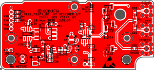
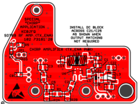
Fox Transmitter Power Amplifier

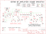
This is the amplifier board for use with the 102-73181-10 boards.
It can be used for normal CW operations and with the wildlife tracker feature.

Circuit Board Image
102-73181-28 Board


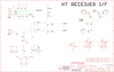
Schematic Image
102_73181_28 Schematic


On the second page of the schematic there is a rather simple RF path from DB$2 through input matching, input attenuation, and DC block into the MMIC gain stage.
On the output of the MMIC amplifier is power (through L1) and output matching and back to the motherboard through DB$4.
Typically the input from the motherboard and the output filter (also on the motherboard) are both 50 Ohms.

If the power switching matrix (TX_ENA to L1) is in place, the amplifier will work for all applications.
Software will correctly manage the U1 power switch.
The board can be built without U1 by installing JP1. Several additional parts could then be left out.

In practice, just build all the amplifiers with everything shown on the schematic (i.e. in the parts list) and you're goos to go.


Back to the Top


Software Status

The current software is linked through the tables at the top of the page.
This load takes over 100K of the available 128KB program flash memory.

This version has a fairly complete command set to allow the fox transmitter to operate in a variety of modes.
We can operate in a single channel mode where all transmitters time share one frequency.
We can also operate in a multi channel mode where all transmitters operate on unique frequencies.
A combination of these two modes may also be programmed.

The TOY clock allows all setup to be performed well in advance of deployment.
The transmitter may be time-locked any time prior to the hunt.
This time synchronization may be accomplished using a host system (through the USB port) or using a synchronization cable where one of the units is assigned the role of a master time source.

The frequency control table has entries for multiple cyrstals making it somewhat feasible to select a crystal that will generate desired frequencies.


Back to the Top


GPS Termination

New projects for this winter...

Place a GPS receiver on the roof, one with PPS (pulse-per-second), and bring the signals into the shack.
The targeted GPS in this case is a Garmin GPS18-LVC, which has TTL level outputs and takes 5 volts.
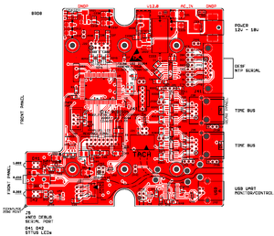
This GPS Repeater board is placed near the GPS receiver to provide power (5 Volts) to the GPS and to drive the NMEA and PPS signals back down to the shack.

Down in the shack another GPS Repeater board receives the NMEA and PPS signals and presents on a standard serial connector (DE9F). Using NTP the computer in the shack can lock on to UT with microsecond precision (note that connecting via USB, although possible, reduces timing precision to the tens of millisonds).
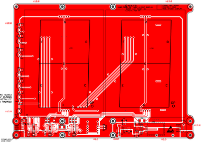
The repeater has an on-board processor that is used to monitor the NMEA traffic and drive a local 7-segment display. Multiple instances of the larger display can be configured to display multiple time zones if desired.

Circuit Board Image
The GPS Repeater Board Schematic

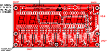
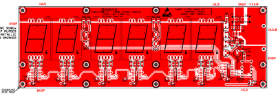
Circuit Board Image Circuit Board Image Circuit Board Image
The Display Boards
The 7-segment displays are 0.56", 1" and 4" respectively.

Connectors on the repeater board (from the bottom right edge) are a USB port to monitor and configure the GPS18-LVC, two time bus ports to receive and repeat the GPS signals. A DE9F serial connector to allow connection to a host system running NTP, and finally the power connector.
The remote repeater cam receive power through the time bus if the GPS current requirements aren't excessive. The voltage regulator is a switch mode device so supplying 12V to 18V to the repeater in the shack reduces the current that moves across the time bus.

Valid HTML 4.01
      Transitional

Last verified 19 Jan 2021, email obfuscator incompatible!